2019W2:Page4
HYBRID COMPONENTIALITY 2.2: D2RP&O
ONLINE CONTENT & APPROACH
This online workshop introduces students to computational design strategies for Design-to-Robotic-Production (D2RP) in order to achieve material and process efficiency in architecture. Students are asked to identify aspects related to robotic production that are relevant for the Off-Earth Habitat project (http://cs.roboticbuilding.eu/index.php/Shared:2019Final) and map those onto the proposed schematic designs. The exercise focuses on hybrid componentiality, which implies that components of various materials and properties are interconnected to establish together a multi-performative whole.
Two D2RP studies are proposed:
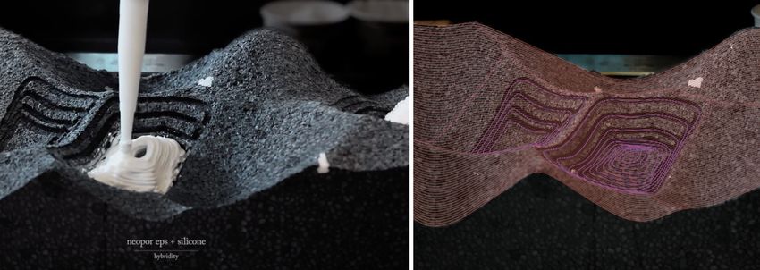
1. Subtractive D2RP: The development of a structurally optimized wall/ceiling/floor component milled from EPS,
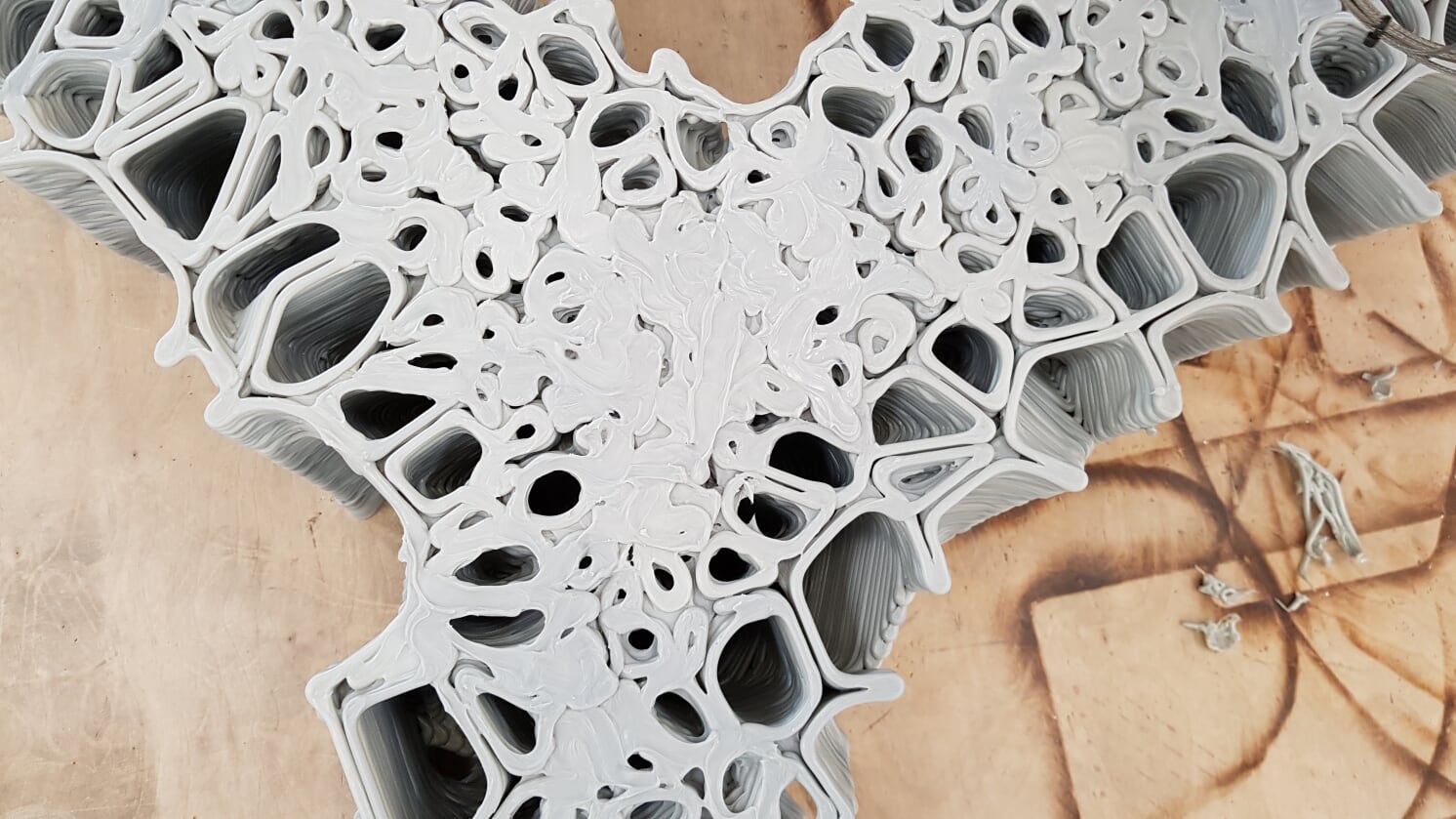
2. Additive D2RP: The development of a 3D printed acoustically optimized layer on top of the milled wall/ceiling/floor component.
Students will be introduced to D2RP through online tutorials and lectures combined with 2 video-conference sessions per week scheduled to take place per group. If one video-conference session will focus on discussing progress of the design, the other one focuses on computational strategy and technical issues. Each group will organize additional video-conferences, where ideas will be exchanges and tasks will be distributed within the group at their own discretion. First two weeks are reserved for developing the design and the computational strategy, while in the third week the focus will shift to prototyping. The actual robotic prototyping will be implemented by tutors and will be streamed implying that students can see in real time the prototyping process but are not physically present on site. This will be an interactive process, which require students to actively participate in the process, give feedback and if needed propose changes in approach and strategy.
DELIVERABLES
a. 1 to max. 2 minutes video of D2RP process,
b. Report (1500 words) consisting of textual and photo/graphical documentation of physical prototypes and design to fabrication process developed during the semester,
c. Clean Rhino and Grasshopper files and refined version D2RP procedures,
d. 3D printed model, 1:1 prototypes, and tests.
COORDINATORS & TUTORS
Henriette Bier, Arwin Hidding, and Vera Laszlo
STUDENTS
Groups 1, 2, 3 and 4 (https://docs.google.com/spreadsheets/d/1DTZlPH5ZMk7LENBdv8eCSv-eJQR493fZfO4wktb_WMk/edit#gid=0)
ONLINE TUTORIALS
Documentation Acoustics
- the rays represent sound waves (mid to high frequencies)
- the vectors indicate the direction of the sound rays
- a linear sound source shows the reflections and the effect of the geometry more clearly
- how many rays indicate the resolution of the calculation
- the resolution is a balance between calculation time and seeing the effect of the rays properly
- the area where the sound rays come from is the sound source
- it depends on the physical sound source, what kind of geometry you would use for this
- if the sound source is a human, a spherical sound source is more realistic, with rays going in all directions
- the nb-bouces represent the number of reflections that the rays bounce around in the space
- the material properties are neglected in this script
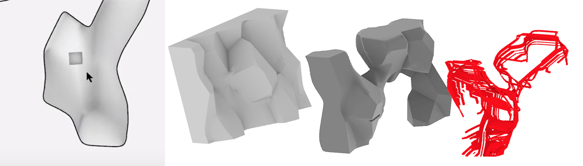
Documentation Structural Analysis
- the resolution of the mesh determines the calculation time and accuracy
- specify supporting points and loads based on the most realistic physical conditions on site
- identify the correct material, along with the material properties
- red stress lines = compression, blue stress lines = tension
- the relative density of the stresslines indicate the concentration/intensity of stresses
Documentation 3D Printing
- the angles of the geometry are -45 to +45 to the printing bed in order to print without supporting material
- layer height 1.4mm
- layer width = 5 to 10 mm
- max size based on reachability of the robotic arm = 500 x 1400 x 1800 mm (rough estimate, it is better to print smaller)
- material is PP
- preferably continuous toolpaths
- the printing time is 27 seconds per layer
- company = 3D-RobotPrinting
Documentation Milling
- the following parameters determine the resulting surface geometry on the prototype:
- the shape and size of the bit
- the angle of the robotic arm, this is the angle that the bit touches the surface of the EPS
- the tool paths, if the toolpaths are close together the surface becomes smoother, further apart creates the surface textures
- milling speed
- max size = 200 x 500 x 600 mm
Documentation Voronoi Cells
- the voronoi cells are generated based on center points
- the density of the point cloud determines the cell sizes
- so if the points are closer together the cells will become smaller
- scaling the geometry vertically creates cells that are mostly printable (not a perfect solution)
- all the cell walls should be -45 to +45 in relation to the printing bed
MILLING BITS and 3D PRINTING
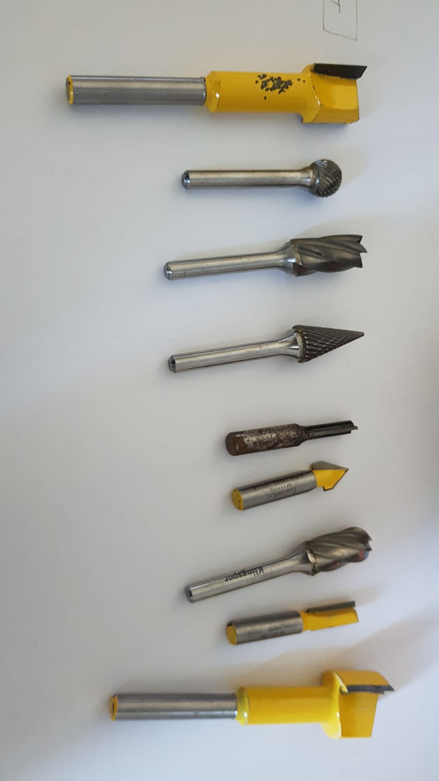
Documentation Milling Bits
- the bit on the most left and right are used for material removal
- the maximum depth for the material removal is 10 mm
- so if you have to remove 80 mm of material you need 8 passes, every time 10 mm deeper into the EPS
- the selected bit for the final pattern determines the surface textures
ONLINE LECTURES